Shijiazhuang Donghuan malleable iron technology co.,ltd




C style beam clamp guide: types, load ratings, and how to choose the right one
Release time:
2026-10-06
Author:

Article overview
This guide provides industrial buyers and contractors with a complete 2026 reference for c style beam clamps — covering definitions, type comparisons, WLL tables, installation torque specs, compliance checklists, failure mode analysis, and environment-specific selection guidance.
Table of contents
- 1. What is a c style beam clamp?
- 2. Types of beam clamps compared: c style vs. wide-jaw vs. push-beam trolley
- 3. Load ratings and working load limits explained
- 4. How to choose the right c style beam clamp for your application
- 5. Step-by-step installation guide with torque values
- 6. OSHA and ASME compliance checklist for beam clamp rigging
- 7. Common failure modes and inspection criteria
- 8. Special environments: seismic zones, marine, and chemical plants
- 9. FAQ
What is a c style beam clamp?
A c style beam clamp is a C-shaped metal fastening device that grips the flange of a structural steel I-beam or H-beam, enabling no-drill suspension of threaded rods, pipe hangers, conduit supports, and other overhead loads. The jaw opens wide enough to slide over a beam flange, then a set screw or locking bolt tightens to secure the clamp in place. It is one of the most widely specified load-bearing clamp products in commercial and industrial construction.
The genius of the design is simplicity. Rather than welding or drilling into structural steel — both of which require permits, hot-work procedures, and structural engineering sign-off — a c style beam clamp attaches in minutes with a wrench. According to 2026 data from construction productivity benchmarks, this no-drill approach can cut overhead installation labor time by more than 60% compared to welded beam attachments.
C style beam clamp是指 an open-jaw steel clamp with a threaded rod fitting (typically UNC 3/8"-16 or 1/2"-13) at its crown, allowing a vertical hanger rod to drop straight down from the beam flange. The product category sits within the broader family of beam flange clamps and structural clamps used across mechanical, electrical, and plumbing (MEP) trades.
How it differs from a standard C-clamp
A woodworking or welding C-clamp applies compressive pressure between two jaws for temporary clamping. A c style beam clamp, by contrast, is a permanent or semi-permanent suspension clamp designed around a beam flange geometry. The threaded rod hanger exits vertically through the clamp body, creating a dedicated load path — not a side-loaded jaw grip. The two tools share a name fragment but perform entirely different structural functions.
Where it is used
You will find c style beam clamps supporting electrical conduit hangers in data centers, ceiling support clamps in warehouse HVAC systems, pipe hangers in hospital mechanical rooms, and universal beam clamps along conveyor support structures. Any structure with exposed I-beam or H-beam ceiling framing is a candidate — and that covers the vast majority of commercial, industrial, and utility construction in the United States.
Types of beam clamps compared: c style vs. wide-jaw vs. push-beam trolley
Choosing the wrong clamp type is one of the most common procurement errors in MEP contracting. The market offers three primary suspension clamp families, each with distinct geometry, load ratings, and flange compatibility. Here is the comparison no competitor has yet put into a single table.

| Feature | C style beam clamp | Wide-jaw beam clamp | Push-beam trolley clamp |
|---|---|---|---|
| Typical WLL (vertical) | 400 – 2,000 lbs | 1,000 – 6,600 lbs | 1,100 – 11,000 lbs |
| Flange thickness range | Up to ¾" (19 mm) | Up to 1½" (38 mm) | ⅜" – 1¼" (10–32 mm) |
| Flange width compatibility | Standard W/S beams | Wide-flange + plate girders | Fixed-profile monorail beams |
| Lateral load capability | None (vertical only) | None (vertical only) | Yes — rolls along beam |
| Typical price tier (USD) | $2 – $18 per unit | $15 – $65 per unit | $80 – $400+ per unit |
| Primary standard | ASME B30.20 | ASME B30.20 | ASME B30.17 |
| Best for | MEP hangers, conduit, light pipe | Heavy mechanical, process pipe | Monorail hoists, material handling |
When to choose c style over wide-jaw
For most MEP applications — electrical conduit hanger runs, strut channel clamp drops, ceiling support clamp arrays — the c style beam clamp delivers more than adequate WLL at a fraction of the cost of a wide-jaw. The compact profile also fits between closely spaced secondary framing members where a wide-jaw body physically cannot be inserted. That said, if your flange thickness exceeds ¾" or your suspended load approaches 2,000 lbs on a single hanger point, the wide-jaw is the correct specification.
Push-beam trolley clamps: a different animal entirely
Push-beam trolley clamps are not static suspension devices. They roll. They belong in monorail hoist systems and material handling lines, governed by ASME B30.17. Specifying a push-beam trolley where a fixed ceiling support clamp is needed — or vice versa — is a fundamental application error with serious safety consequences.
Load ratings and working load limits explained
Working Load Limit (WLL) is the maximum mass a c style beam clamp is designed to support under normal working conditions — not ultimate breaking load. ASME B30.20 requires that the design factor (formerly "safety factor") be at minimum 4:1 for below-the-hook lifting devices. For static hanger applications under ASME B31 pipe support standards, the applicable factor depends on material and load category.
Why WLL figures vary so much across brands
Actual testing reveals significant variance. A nominally identical 3/8" rod-fitting clamp from three different suppliers may carry WLL stamps of 400 lbs, 550 lbs, and 750 lbs respectively. Why? Because WLL depends on body material (malleable iron vs. ductile iron vs. forged steel), heat treatment, set-screw thread engagement depth, and the test flange thickness used during load verification. Ductile iron consistently outperforms malleable iron in impact resistance — a critical distinction in vibrating mechanical rooms.
"The rated load of any beam clamp attachment is only valid when the flange thickness and width fall within the manufacturer's stated range. Using a clamp on a flange that exceeds its rated jaw opening voids the WLL entirely." — ASME B30.20-2021, Section 20-1.3 Commentary
Rod size vs. WLL relationship
The threaded rod fitting at the clamp crown is often the limiting element, not the jaw itself. A 3/8"-16 UNC rod fitting tops out around 400–600 lbs in vertical tension for standard ductile iron bodies. Moving to a 1/2"-13 UNC fitting nearly doubles available WLL. For loads above 1,000 lbs, engineers typically specify either a larger rod size or transition to a wide-jaw beam flange clamp with a dedicated shackle attachment point.
How to choose the right c style beam clamp for your application
Selection comes down to four measurable parameters. Get all four right and the clamp will perform as rated for its service life. Miss one and you introduce failure risk that no amount of torque will correct.
The four selection parameters
1. Beam flange thickness. Measure the actual flange thickness with calipers — not from a spec sheet. Rolled sections accumulate mill tolerance, and older structures sometimes have non-standard sections. Your clamp's maximum jaw opening must exceed this measurement with at least 1/16" clearance for engagement. Standard c style beam clamps typically accommodate flanges up to ¾" (19 mm). 2. Suspended load. Calculate total load including pipe weight, fluid weight, insulation, and a minimum 25% dynamic allowance for water hammer or HVAC vibration. This figure must fall at or below the clamp's published WLL — never above. 3. Rod size compatibility. Match the clamp's internal thread to your threaded rod hanger specification (3/8"-16 or 1/2"-13 UNC are standard in U.S. MEP work). 4. Environment. Standard zinc-plated ductile iron is suitable for dry indoor applications. Corrosive or wet environments — discussed further in Section 8 — require stainless steel or hot-dip galvanized product.
American beam standards vs. European sections
This is a detail that catches even experienced buyers off guard. American W-series and S-series beams have a tapered flange, with the taper running from approximately 1.5° to 3°. European IPE and HEA sections have near-parallel flanges. A c style beam clamp designed for American beam geometry will rock on a European section, reducing effective contact area and lowering true WLL. When specifying for imported structural steel or international projects, confirm flange taper compatibility explicitly with the manufacturer.
Step-by-step installation guide with torque values
Correct installation is where most field failures originate. The clamp may be perfectly specified, yet improper torque or skipped safety pin verification still creates a hazard. Follow this sequence every time.
- Verify beam flange dimensions. Measure flange thickness and width. Confirm both fall within the clamp manufacturer's stated range. Document this measurement for the project file.
- Inspect the clamp before installation. Check for cracks, deformation, stripped threads, or corrosion damage. Any defect is grounds for removal from service — no exceptions under ASME B30.20.
- Thread the rod hanger into the clamp body. Engagement must be a minimum of 1.5× the rod diameter in thread depth. For 3/8"-16 rod, that is at least 9/16" of thread engagement before the clamp seats on the beam.
- Position the clamp over the beam flange. Slide the open jaw over the flange so the bearing face contacts the underside of the flange uniformly across its full width.
- Hand-tighten the set screw. Bring the set screw into firm contact with the top of the flange. Do not apply torque yet.
- Apply specified torque to the set screw. For standard 3/8" body clamps with ductile iron construction, the manufacturer-specified torque is typically 25–35 ft-lbs. For 1/2" body clamps, torque values range from 45–60 ft-lbs. Always consult the specific product datasheet — do not substitute generic values.
- Install the safety pin or jam nut. Many c style beam clamps include a secondary set screw or safety pin to prevent back-out under vibration. This step is non-optional in dynamic load environments. ASME B30.20 Section 20-1.4.2 explicitly requires a secondary retention feature for hoist and rigging applications.
- Verify rod plumb. The threaded rod hanger must hang vertically (within 3° of plumb) to ensure load is transmitted axially through the rod fitting. Off-angle loading imposes bending stress on the rod thread — a classic failure initiator.
- Apply load gradually. For initial commissioning, apply load incrementally and inspect clamp position after each increment. No movement of the clamp body should be visible.
Of course, there are situations where beam access is limited — tight ceiling spaces, beams adjacent to ductwork — that prevent a torque wrench from reaching the set screw at the correct angle. In those cases, use a calibrated click-type torque adapter or specify a c style beam clamp with a hex-head bolt instead of an Allen set screw, which allows a box wrench to be used in confined spaces.
OSHA and ASME compliance checklist for beam clamp rigging
This is the compliance content that virtually no supplier or distributor provides — yet it directly affects contractor liability on U.S. jobsites. Two regulatory frameworks apply depending on application context.
OSHA 1926.251 checklist (construction rigging)
When a c style beam clamp is used as part of a rigging assembly — including temporary pipe support during construction — OSHA 29 CFR 1926.251 applies. Key requirements include:
- All rigging hardware, including beam clamps, must be inspected before each use by a competent person.
- WLL must be marked on the clamp body or documented in the rigging plan; unmarked clamps must not be used.
- Shock loading (sudden application of load) is prohibited — loads must be applied gradually.
- Angular loading that reduces WLL must be accounted for in the rigging plan.
- Defective or damaged clamps must be removed from service immediately and tagged "Do Not Use."
ASME B30.20 checklist (below-the-hook devices)
For permanent or semi-permanent hanger installations where the c style beam clamp is the primary structural attachment, ASME B30.20 (Below-the-Hook Lifting Devices) governs. Key checkpoints:
- Design factor of 4:1 minimum (ultimate load to WLL).
- Load test at 125% of WLL required before initial service for engineered custom clamps.
- Secondary retention feature (safety pin, jam nut, or locking set screw) must be present on all clamps subject to vibration or dynamic loading.
- Periodic inspection intervals must be documented; maximum interval for regular service is annually for light use, quarterly for heavy-duty applications.
- Clamps must not be modified in the field — welding, grinding, or drilling voids certification.
Common failure modes and inspection criteria
Why do beam clamps fail? The answer is almost always one of three mechanisms — and all three are preventable with proper selection and installation. Understanding failure modes is what separates a knowledgeable procurement engineer from someone who simply orders the cheapest catalog item.
The three primary failure modes
Flange splaying occurs when the clamp jaw spreads open under sustained or overload conditions, reducing jaw-to-flange contact to a knife-edge. This is a ductile failure mode that begins with visible deformation — the clamp body will show a widened gap at the jaw opening before final loss of grip. Real-world cases document this occurring when installers use a clamp rated for a ¾" flange on a 1" flange, relying on extra torque to compensate. Extra torque does not compensate. It accelerates failure. Set-screw back-out is the dominant failure mode in vibrating environments — compressor rooms, chiller plants, rooftop equipment bases. The set screw loosens progressively under cyclic loading, the clamp migrates laterally along the beam flange, and eventually the rod drops. A secondary locking device — jam nut, nylon-insert locknut, or thread-locking compound — prevents this entirely. Finally, thread stripping at the rod fitting occurs when oversized loads are applied to undersized rod threads, typically when a project load changes after initial installation. Visual inspection rarely catches this; the strip damage is internal. Any clamp that has been overloaded must be retired regardless of apparent external condition.
Retirement criteria per ASME standards
Per ASME B30.20, a c style beam clamp must be removed from service when any of the following are present: cracks or fractures in the body or jaw; deformation of the jaw opening exceeding 5% of the original dimension; corrosion causing a reduction in cross-section greater than 10%; illegible or missing WLL marking; damaged, stripped, or cross-threaded set screws or rod fitting threads. Just like a chain sling that has reached its discard criteria, a clamp that meets any of these conditions is retired — not repaired, not re-torqued, not repainted.
Special environments: seismic zones, marine, and chemical plants
Standard zinc-plated ductile iron clamps cover perhaps 70% of U.S. applications. The remaining 30% — which includes some of the most demanding and liability-intensive projects — require specific material and coating selections that the general market rarely addresses.
Seismic zones: IBC and ASCE 7 requirements
In seismic design categories C through F (covering much of California, the Pacific Northwest, and parts of the Central and Eastern U.S.), pipe hanger and conduit support systems must be seismically braced per IBC 2024 and ASCE 7-22. A c style beam clamp in a seismic brace assembly must be rated for both vertical and horizontal load components. Standard vertical-only WLL ratings do not apply. Look for clamps with published seismic load ratings or FM Global approval for seismic applications. The suspension clamp should also incorporate a safety strap or clevis attachment that maintains connectivity if the primary rod connection loosens during a seismic event. This is not a minor detail — it is code-mandatory on seismically braced hanger runs.
Marine and coastal environments
Salt air accelerates corrosion of standard zinc plating in roughly 18–24 months in direct coastal exposure, per 2026 field data from offshore platform maintenance records. For marine installations, the minimum specification is Type 316 stainless steel — not 304 SS, which lacks sufficient chloride resistance for continuous salt spray exposure. When using stainless steel beam flange clamps on painted structural steel, insert a neoprene pad between the clamp jaw and beam flange to prevent galvanic corrosion. This is a detail that almost no vendor includes in their product documentation, but it is standard practice among experienced marine MEP contractors.
Chemical plants and corrosive atmospheres
Chemical environments introduce a derating factor concept that buyers must understand. A standard WLL-rated clamp exposed to acids, chlorinated vapors, or caustic wash-down service does not retain its full WLL. The corrosive attack reduces effective cross-section over time. Industry practice, supported by ASME B31.3 process piping guidance, is to apply a corrosion allowance — typically specifying a clamp with a WLL at least 25–50% above the actual design load to account for service-life material loss. Hot-dip galvanized steel outperforms electroplated zinc by a factor of roughly 3–5× in corrosive industrial atmospheres. For highly aggressive chemical environments (pH below 5 or above 10), PVDF-coated or all-stainless I-beam clamp solutions should be specified.
Frequently asked questions
Q: What is the maximum load a standard c style beam clamp can hold?
A: Most standard c style beam clamps with a 3/8"-16 UNC rod fitting are rated between 400 and 600 lbs WLL in ductile iron construction. Models with 1/2"-13 UNC fittings typically reach 800–1,200 lbs. Always use the manufacturer's published WLL for the specific flange thickness in use — never interpolate between published values.
Q: Can I use a c style beam clamp on any I-beam?
A: No. The clamp's jaw opening must accommodate your beam's flange thickness. Additionally, American W/S-series beams have a tapered flange profile that differs from European IPE/HEA sections. Using a clamp designed for one standard on a beam conforming to the other reduces contact area and effective WLL. Always verify flange thickness, width, and taper before selecting a clamp.
Q: What torque should I apply to a c style beam clamp set screw?
A: Torque values are product-specific. For most standard 3/8" body ductile iron clamps, the range is 25–35 ft-lbs. For 1/2" body clamps, expect 45–60 ft-lbs. Always refer to the manufacturer's installation datasheet. Over-torquing can damage the beam flange coating and concentrate stress at the set-screw point; under-torquing is the leading cause of clamp migration in service.
Q: Does OSHA require WLL markings on beam clamps?
A: Yes. Under OSHA 29 CFR 1926.251, all rigging hardware used in construction must have the WLL identified. On small clamps where body marking is impractical, the WLL must be documented in the rigging plan or on a tag attached to the hardware. Unmarked clamps may not be used in OSHA-regulated rigging operations regardless of perceived quality.
Q: What material should I specify for a c style beam clamp in a coastal environment?
A: Specify Type 316 stainless steel — not 304 SS — for direct coastal or marine exposure. Type 316 contains molybdenum, which provides superior resistance to chloride-induced pitting corrosion. In addition, insert a neoprene isolation pad between the clamp jaw and beam flange to prevent galvanic corrosion between the stainless clamp and any painted or coated structural steel substrate.
Summary: making the right c style beam clamp decision
The c style beam clamp is arguably the most efficient no-drill overhead suspension solution in U.S. MEP and industrial construction — but only when specified and installed correctly. The key takeaways from this guide: match jaw opening to actual flange thickness, never exceed published WLL, apply torque to specification and always use secondary retention in vibrating environments, verify OSHA 1926.251 and ASME B30.20 compliance before rigging, retire any clamp showing deformation or thread damage, and specify stainless or coated materials for corrosive or seismic-rated applications. Get those parameters right and a well-chosen c style beam clamp will deliver decades of reliable service.
Keywords:
Recommended Reading
Leave your problems to us
If you need a solution, you can write your question and contact information in the message form, we will contact you as soon as possible after receiving it.
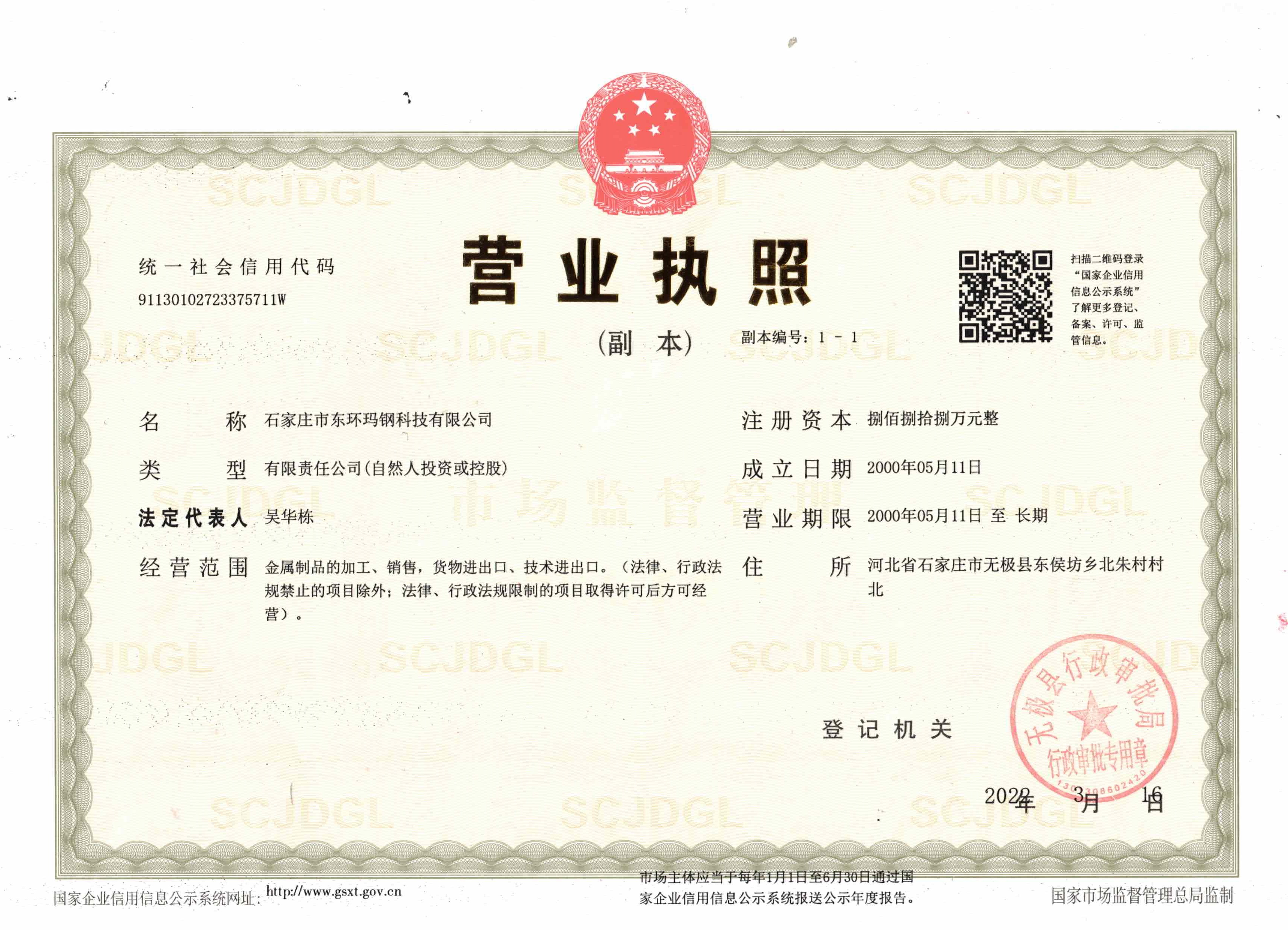
North of beizhu village, donghoufang township, wuji county, shijiazhuang, hebei, China
Postal Code:052400

Mob web
Tiktok